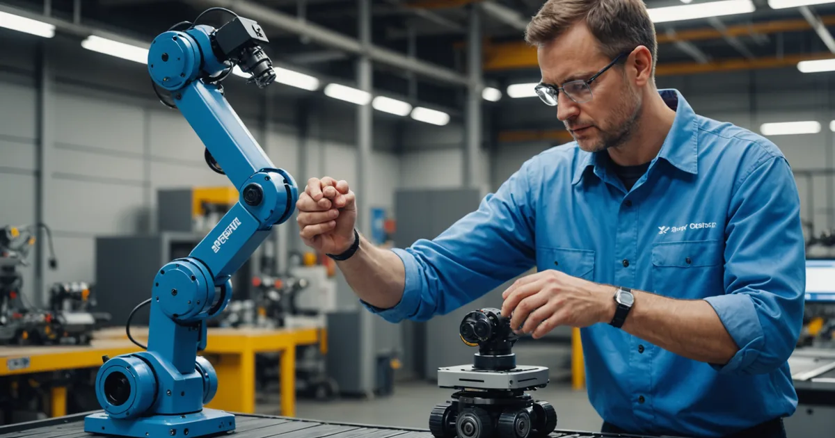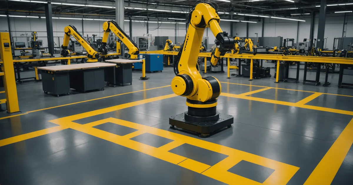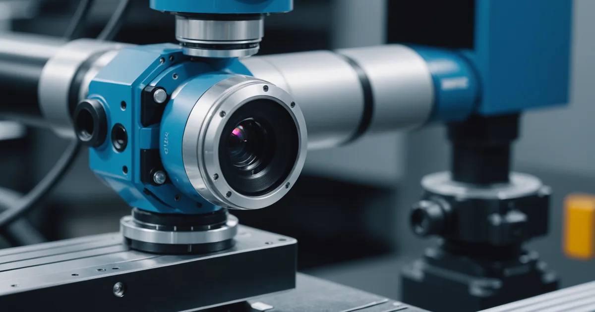
The depth camera on the arm is doing two things at every station: it maps the geometry of the work area so the motion planner can generate collision-safe trajectories, and it runs a real-time pose estimation pipeline that tells the arm where the part actually is before each pick or place. The second function is what makes the arm useful for assembly assist and orientation checking, and it is worth explaining in some detail what "real-time pose estimation" actually means technically, because the marketing language around vision-guided robotics is often imprecise enough to obscure what the system can and cannot do.
What the depth camera sees and how it models it
The arm uses a structured-light depth camera mounted at a fixed offset from the wrist flange. Unlike a single RGB camera, a structured-light sensor projects a known infrared pattern onto the scene and measures the deformation of that pattern to compute per-pixel depth. The output is a 3D point cloud: for each pixel in the camera's field of view, a (x, y, z) coordinate in the camera's reference frame.
From this point cloud, the perception pipeline runs a surface segmentation step to identify planar regions (the tops of parts, fixture faces, conveyor surfaces). For parts with known CAD geometry, the pipeline uses a model-based fitting approach: it takes the expected point cloud signature of the target part in its reference orientation and searches the observed point cloud for a match, using an iterative closest point (ICP) algorithm to converge on the 6-DOF pose estimate (three translational, three rotational degrees of freedom).
The practical output of this pipeline for an assembly assist task is a pose estimate: "the part is at position (x, y, z) relative to the camera, with orientation (roll, pitch, yaw)." The arm's controller uses this estimate to adjust the approach trajectory in real time before the pick or assembly contact move.
The orientation check function: how it works at an assembly station
One of the more useful things this perception capability enables is inline orientation checking during an assembly sequence, not just at a separate inspection station after the fact.
Here is a concrete example from one of our early deployments. A Tier-3 stamped metal parts supplier had a sub-assembly station where a small bracket was inserted into a housing in a specific orientation. Two orientations of the bracket were physically possible: the correct one and a 180-degree rotation of it. Both orientations allowed the bracket to seat in the housing. The difference was only detectable later in the process when a downstream drilling operation would hit a void in the wrong location if the bracket was inverted.
The arm's task at this station was to pick the bracket from a feeder tray and seat it in the housing. The depth camera pose estimation step, running before each pick, identified whether the bracket was in the correct or inverted orientation on the feeder tray. If the estimated pose matched the correct orientation reference (within the tolerance window set during commissioning), the arm proceeded with the pick. If the pose estimate matched the inverted orientation, the arm executed a pre-grasp 180-degree rotation to correct the orientation before proceeding to the placement move.
This is not a separate inspection step. It happens in the 40 to 80ms pose estimation window before the arm commits to the pick trajectory. The operator does not see a separate check; from their perspective, the arm just places brackets correctly every cycle. The orientation error either never happens (feeder presents correct orientation), or is silently corrected before the assembly (feeder presents inverted orientation, arm corrects), or is flagged as an out-of-range pose error if the part is presented in an orientation the system has not seen during commissioning (feeder jammed, wrong part type, etc.).
The quality check pass at end-of-line
A separate use of the same perception infrastructure is the end-of-line quality check pass. After the arm completes its assembly cycle, it can execute a short inspection trajectory: moving to a viewpoint position above the completed assembly, acquiring a fresh depth scan, and comparing the observed geometry to the reference model of the correct completed assembly.
The comparison is geometric, not visual: the pipeline computes the point cloud difference between the observed assembly and the reference, and flags if any region of the assembly shows more than the configured deviation threshold (typically 2 to 5mm depending on the application). This can detect common assembly errors:
Missing components. If a component was not inserted (fastener missing, clip not seated, label not applied), the point cloud in that region will be missing the geometry that should be present. The deviation from reference in that region exceeds the threshold and the system flags the cycle.
Proud or tilted insertions. A component that was not fully seated will show geometry that is elevated above the reference position. The deviation threshold catches this if the height difference is within the sensor's depth resolution (typically 0.5 to 1mm for structured-light sensors at this range).
Wrong component type. If a different part variant was accidentally used (different height profile, different geometry), the point cloud will not match the reference model for the correct variant, and the system will flag the difference.
What this does not replace
The depth camera orientation check is a useful in-process quality gate, but it operates on geometric properties that the 3D sensor can measure. It does not substitute for electrical tests, torque verification, or visual inspection for surface defects that are not geometric in nature. If your assembly quality requirements include a fastener torque check, a continuity test, or an optical appearance inspection for surface finish, those still need dedicated test stations or instruments.
The geometric check also has a sensitivity floor set by the sensor's depth resolution and the accuracy of the reference model. For assemblies where the distinction between correct and incorrect is at the submillimeter level (for example, a pressed bearing that is either fully seated or 0.3mm proud), the check may not be reliable enough to use as the sole quality gate. The appropriate role for the depth camera inspection is catching the larger-delta failures (missing parts, obviously misaligned components, gross orientation errors) that currently pass manual inspection stations at some rate due to operator fatigue late in a shift.
We are direct about this with every deployment: the depth camera quality check reduces the rate of downstream escapes for geometric error types, but it is calibrated to your specific assembly's geometry and validated over a sufficient number of cycles before being treated as a quality gate. Do not configure it as a pass/fail gate without that validation, because the false-positive and false-negative rates depend strongly on your part-to-part dimensional variation and your production lighting conditions, which both need to be characterized on your specific floor.
What the data looks like over time
The perception pipeline logs pose estimates and deviation scores for every cycle. Over a production run of several hundred cycles, this data builds a statistical picture of part presentation variability (how much does the pose estimate vary cycle to cycle?) and assembly quality distribution (what is the distribution of deviation scores on correct assemblies versus flagged ones?).
This data is useful for two things. First, it informs whether the tolerance thresholds set during commissioning are appropriate: if the deviation score distribution for correct assemblies has significant overlap with the threshold, it means the threshold is too tight and needs adjustment. Second, it identifies whether part presentation variability is increasing over time, which can indicate feeder wear or a change in incoming part dimensions. Both are conditions the system can flag before they become production problems.