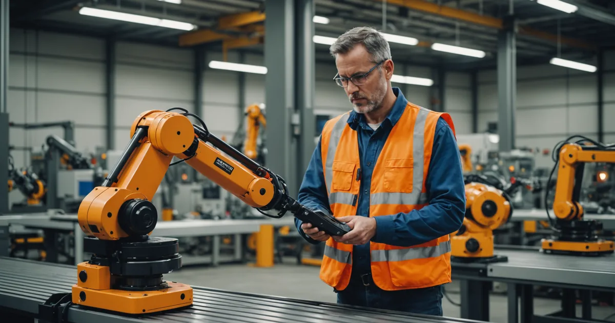
Last Tuesday morning, I was at a Tier-2 stamped-metal parts supplier outside of Flint. Their line had been running a palletizing task on the arm since January. They needed to flip the same station to pick-and-place for a new sub-assembly contract starting Monday. The operations manager, a guy named Ray who has been running that floor for fourteen years, had one question when I arrived: "Do I need to clear the day for this?"
I told him no. He looked skeptical. This is an honest account of how that Tuesday actually went, start to finish, including the one spot where we had to redo a waypoint.
The starting point: what the arm was doing
The palletizing task had been running for about six months. The arm was picking stacked metal stampings from an end-of-line conveyor and placing them in a 4x4 pallet grid pattern. Cycle time was 8 seconds per pick. The gripper was a two-jaw pneumatic unit mounted on a quick-release wrist coupling.
The new task was pick-and-place for a smaller stamped bracket. Incoming parts arrive in a shallow bin via a gravity-feed chute, and the arm needs to pick each part, rotate it 90 degrees, and place it into a fixture tray that holds 12 positions. Tighter tolerances on placement, different gripper geometry, and a different part presentation angle. Not trivial, but well within the arm's capability envelope.
The arm itself had not moved. The station footprint was the same. We were reusing the same physical mounting and the same PLC I/O connections. The only changes were the end-effector and the task definition.
Step 1: Gripper swap and calibration check (9:10 to 9:28 am)
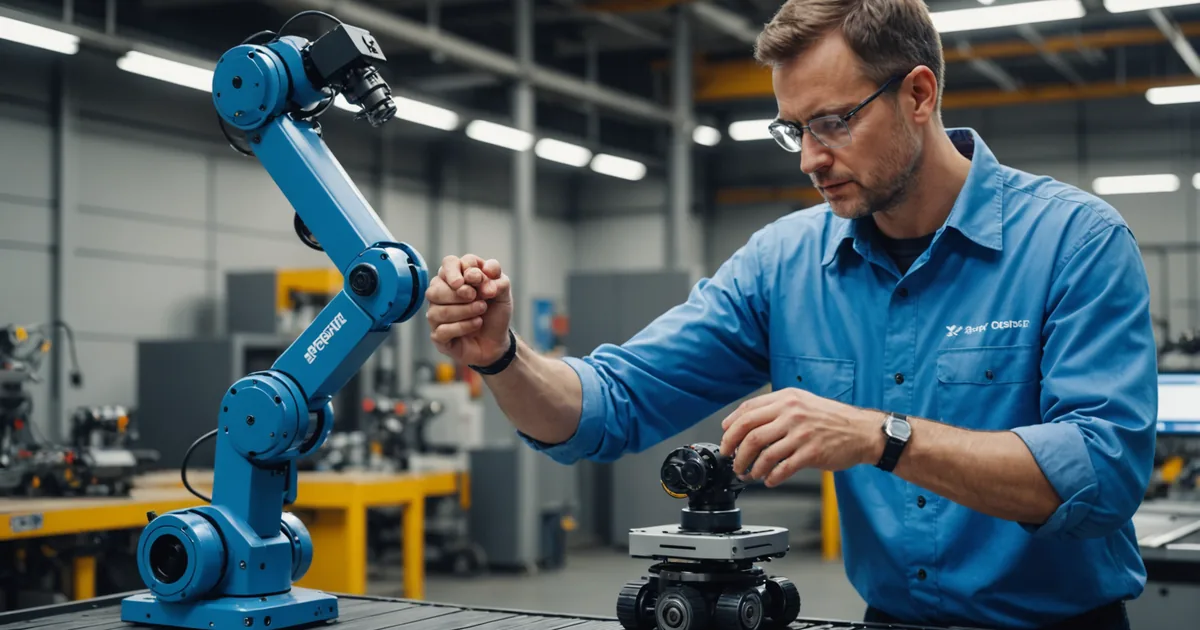
Ray's maintenance tech swapped the end-effector first, about an 8-minute job with the quick-release coupling. The new gripper was a three-finger adaptive unit we had pre-tested on the bracket geometry the previous week at our shop. Once it was mounted, I opened the task software and ran the sensor calibration check from the diagnostics panel.
The calibration check does three things: it verifies the depth camera's spatial reference frame, confirms that the force-torque sensor baseline is within tolerance after the mechanical change, and recalculates the collaborative safety zone envelope accounting for the new end-effector geometry. On this unit, the check takes about 5 minutes to complete. Everything came back nominal. Ray watched the status panel while this ran. He noted that he had never seen a machine tell him its own safety zone before. I told him this was the part that usually takes an integrator a half-day to set up manually.
Step 2: Creating the new task definition (9:28 to 9:52 am)
The task editor starts by asking you to name the task, select the task type from the library, and describe the gripper preset. We named it "bracket-pick-fixture-place," selected the pick-and-place task type, and set the gripper preset to the three-finger adaptive profile we had loaded the previous week.
The task editor then asks for the waypoint count. For a simple pick-and-place with a 12-position fixture, you need at minimum four waypoints per fixture column: approach, pick, lift, and place. We added two additional waypoints for the 90-degree rotation and for the part-release position over the fixture slot. Six waypoints total.
Before any physical teaching begins, the editor shows you the current safety zone geometry rendered in the 3D preview. The collaborative zone radius had automatically recalculated based on the new end-effector dimensions and the task type's speed profile. We reviewed this with Ray and it matched the physical station layout. The zone boundary fell 480mm from the robot base, well inside the perimeter guarding already in place.
Step 3: Visual teach mode (9:52 to 11:34 am)
This is where most of the time goes, and it is worth describing carefully because it is the part that surprises people who are used to teach pendant programming.
In visual teach mode, the operator physically guides the arm to each waypoint position. The arm is in compliance mode: you move it, it follows, and the depth camera plus inertial measurement system records the position and orientation at each waypoint you confirm. You confirm a waypoint by holding the enable grip and pressing the save button on the wrist-mounted control ring. The system records not just the joint angles but also the orientation of the gripper relative to the part surface as seen by the depth camera.
Ray's maintenance tech, Donovan, did the physical teaching. He had never touched a robot arm before this session. I walked him through the first waypoint: approach position above the bin, 200mm above the expected part surface. He guided the arm there, confirmed the orientation on the camera preview screen, and saved it. The second waypoint was the pick position: down into the bin, gripper aligned with the bracket's grip surfaces. This one took us two attempts because the first attempt had the gripper approaching at a slight angle that would have caused contact with the bin wall on some part presentations. Donovan repositioned, I confirmed the clearance on the preview, and we saved the second version.
Working through all six waypoints took about 40 minutes. The fixture placement waypoints were the most precise, with tolerances around plus or minus 2mm on position and plus or minus 1 degree on orientation to ensure the bracket seated properly in the fixture slot. The depth camera's part-relative pose estimation was carrying most of that precision load, but we still walked through three trial placements to verify that the 12-position fixture coverage was complete across the tray.
Step 4: Collision geometry preview and zone validation (11:34 to 11:51 am)
After all six waypoints are confirmed, the task editor renders the full trajectory as a 3D path preview and runs the collision geometry check. This sweeps the arm through the recorded path and flags any positions where the predicted tool path comes within the collision margin of objects the depth camera saw during the teach session.
We had one flag: the approach path for the bin pick came within 35mm of the gravity-feed chute wall at maximum part-height in the bin. The system flagged this as a caution, not a hard block, because 35mm is inside the caution margin but outside the hard-stop margin for this speed profile. We had two options: adjust the approach waypoint to give more clearance, or reduce the approach speed on that segment. We opted to reduce the approach speed from 250mm/s to 180mm/s on the first two waypoints. The flag cleared.
Ray reviewed the trajectory preview on the screen with us. He asked one question: what happens if someone walks into the zone while the arm is running. I walked him through the speed-and-separation monitoring response: the arm slows as a person enters the monitored zone and stops if they cross the inner boundary. This behavior is defined by the collaborative safety mode parameters set during commissioning, which were established at initial installation and had not changed for the new task. The zone geometry itself was updated, but the monitoring logic was the same.
Step 5: Confirmation cycles and production approval (11:51 am to 12:43 pm)
The deploy panel runs three confirmation cycles before enabling production. The first cycle runs at 30% speed with the operator monitoring. The second runs at 60% speed. The third runs at full speed. Between each cycle, the operator reviews the cycle report: any position variance above threshold, any collision geometry proximity events, any I/O timing issues.
Our first full-speed cycle flagged a position variance on waypoint 4, the first fixture placement position. The variance was 3.1mm on the Y axis, above the 2mm threshold we had set. We traced this to a slight inconsistency in how the parts were presenting from the gravity-feed chute: occasionally a bracket would land slightly off-center, and the depth camera's real-time part pose correction was overcorrecting on the Y axis. We tightened the speed profile on the approach-to-fixture segment, which gave the correction algorithm more time to resolve before the place event. Third cycle ran clean.
Ray signed off on the deploy panel at 12:43 pm. The arm went into production mode on the new task. He ate lunch. The arm ran 47 cycles during his lunch break without a fault.
What this tells us about changeover expectations
Total elapsed time from gripper swap to production: 3 hours and 33 minutes. We spent roughly a quarter of that time on physical teaching, a quarter on the calibration and task setup, and about half on confirmation cycles and the one waypoint correction.
A few honest notes on what this does not tell you: this plant had already been running the arm for six months, so Donovan had some comfort with the hardware even if he had not done a teach session before. A first-ever deployment on a new line would add time for the operator orientation. The geometry of this particular task was also well-suited to visual teaching, with consistent part presentation and a fixed fixture. Tasks with high part-orientation variability or very tight placement tolerances may take longer in teach mode, and some will require additional waypoints to handle variability at the extremes of the part presentation range.
That said, the core claim holds: a plant manager who has never programmed a robot can retask a running arm in an afternoon without calling an integrator, provided the task geometry is within the arm's capability and the operator spends the time the teach session actually requires. For this station, on this task, that time was under four hours.
Ray sent me a message the next morning. The arm ran 340 cycles overnight. No faults. He asked when we could do the second station.