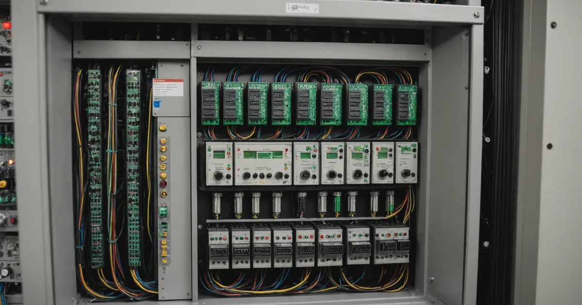
The PLC integration question comes up on almost every deployment. The plant's existing line has a PLC orchestrating the conveyor, the light curtains, the cycle start signals, and sometimes half a dozen other I/O devices. The arm needs to fit into that control hierarchy without requiring the plant to rebuild the PLC program from scratch. How hard that is depends on which protocol the PLC and arm speak, and whether the I/O signals the arm needs are already present in the PLC's output mapping.
This article covers the two protocols we see most often at Tier-2 and Tier-3 facilities: EtherNet/IP for Allen-Bradley-heavy environments and Modbus TCP for everything else. These are industrial-standard protocols with well-defined specifications; what follows describes how the handshake works in practice, not a vendor-specific implementation.
What the arm actually needs from the PLC
Most cobot deployments require a small set of PLC signals. Understanding what the arm expects makes it easier to map those signals to existing PLC outputs or to add them with minimal program modification.
At minimum, the arm needs:
Cycle start. A discrete input signal (typically 24V DC) that tells the arm to begin the next task cycle. On most stations this comes from the same source that starts the rest of the line cycle: a conveyor presence sensor, a fixture-loaded confirmation, or a manual cycle start button.
Emergency stop integration. The arm's safety circuit must be integrated with the plant's E-stop network. This is typically a hardwired safety relay circuit, not a network protocol signal. The arm's safety inputs connect to the same E-stop loop that covers the rest of the station, so a single E-stop event stops both the arm and the connected equipment.
Arm status outputs. The arm outputs a cycle-complete signal, a fault status signal, and optionally a ready-to-receive signal. These go back to the PLC to allow the line logic to sequence correctly: do not start the next conveyor advance until the arm signals cycle-complete; flag an operator call if the arm signals fault.
Optional but common: a task-select input for stations where the PLC needs to tell the arm which task to run (useful when the arm stores multiple task configurations and the product changeover triggers a task switch automatically), and a speed-override input for stations where the PLC manages collaborative zone reduction based on upstream sensor data.
EtherNet/IP: what the connection looks like
EtherNet/IP is a widely used industrial protocol based on CIP (Common Industrial Protocol) transported over standard Ethernet. It is the native protocol for Allen-Bradley ControlLogix, CompactLogix, and MicroLogix PLCs, and it is supported by a wide range of other industrial equipment.
The arm acts as an EtherNet/IP adapter (target) and the PLC acts as the scanner (originator). The PLC initiates an implicit messaging connection to the arm at startup, which establishes a cyclic data exchange at a configured rate (typically 10 to 20ms for discrete I/O). The PLC sends its output assembly (the signals it is sending to the arm: cycle start, task select, etc.) and receives the arm's input assembly (cycle complete, fault status, etc.) on each cycle.
From the PLC program perspective, the arm's I/O appears as a set of tags in the controller tag database, exactly like any other EtherNet/IP device. The control logic uses those tags directly. A typical cycle start rung looks like:
ConveyorPartPresent AND NOT ArmFault AND ArmReadyToReceive
  => ArmCycleStart (one-shot rising)
And a typical cycle complete rung:
ArmCycleComplete (one-shot rising)
  => ConveyorAdvance
The EDS (Electronic Data Sheet) file for the arm defines the assembly sizes and data format for the implicit connection. You add the arm as a device in the PLC's I/O configuration using the EDS file, configure the connection parameters (RPI rate, connection type), and the PLC generates the tag structure automatically. First-time setup for a plant with an existing Allen-Bradley environment takes 30 to 60 minutes for someone familiar with Studio 5000, not counting physical wiring.
Modbus TCP: what the connection looks like
Modbus TCP is an older, simpler protocol widely supported by Siemens S7 PLCs, Mitsubishi iQ-R series, and many other controllers. It uses a client/server model: the PLC acts as the Modbus master (client) and the arm acts as the Modbus slave (server). Communication is over standard TCP port 502.
Unlike EtherNet/IP implicit messaging, Modbus TCP is a request/response protocol. The PLC polls the arm's holding registers or coils at a configured rate to read status, and writes to registers or coils to send commands. The data model is simpler: discrete inputs and outputs map to coil registers (single-bit), and multi-word data (such as a task ID or a speed setpoint) maps to holding registers (16-bit words).
A typical Modbus setup for a basic arm integration uses a small number of registers:
Output coils (PLC writes, arm reads): coil 0 = cycle start, coil 1 = E-stop relay (if using Modbus-integrated safety, though hardwired is preferred), coil 2 = task select bit 0, coil 3 = task select bit 1.
Input coils (PLC reads, arm writes): coil 0 = cycle complete, coil 1 = fault active, coil 2 = arm ready.
The PLC logic is similar to the EtherNet/IP case in structure; the difference is that Modbus data is accessed through explicit read/write function blocks rather than as native tags. On a Siemens TIA Portal project, you use the MB_CLIENT instruction to initiate the connection and poll the arm. Response latency is typically 20 to 50ms on a local network, adequate for the discrete I/O signals involved.
Common integration mistakes
A few patterns cause most of the integration problems we encounter at initial commissioning.
E-stop not properly integrated. The arm's hardwired safety input is separate from the network protocol connection. We have seen setups where the PLC's E-stop output is wired to the arm's cycle-inhibit network coil but not to the arm's hardwired safety relay input. The result is that the arm's motion stops on an E-stop command in normal operation, but the arm's power stage is still enabled. This is incorrect. The arm's safety relay input must be in the E-stop loop. This is a commissioning check, not an afterthought.
Cycle-complete signal used as a gate without fault handling. If the downstream PLC logic uses arm cycle-complete as a gate for conveyor advance, and the fault handling logic does not also check for arm fault, a fault condition can cause the line to stall silently. The arm stops mid-cycle, cycle-complete never fires, the conveyor never advances, and the line backs up. Always wire both the cycle-complete path and the fault path into your sequencing logic.
Task-select not updated before cycle start on task change. When the arm has multiple stored tasks and the PLC selects them via a task-select register, the task-select value must be stable before the cycle-start signal fires. If your PLC logic updates the task-select and cycle-start in the same output scan, there is a small window where the arm may receive the cycle-start before the new task-select value is registered. Use a one-scan delay or explicit handshaking to ensure the task-select is confirmed before cycle-start fires.
Network architecture considerations
The arm should be on an isolated industrial network segment, not on the plant's general IT network. This is both a cybersecurity practice and a reliability practice: industrial Ethernet segments have deterministic traffic patterns and are not subject to the broadcast storms and variable latency that can occur on general-purpose office networks. A dedicated managed switch for the automation island, with a controlled uplink to the plant network if remote monitoring is required, is the standard configuration.
If your facility uses multiple protocol islands (an Allen-Bradley segment on one end of the floor and a Modbus segment on the other), protocol converters are available and work reliably for the simple I/O signals involved. We do not recommend bridging through a general IT router if avoidable; latency and packet loss on bridged segments can cause intermittent communication faults that are difficult to diagnose.
The integration scope described here applies to a standard station deployment. Complex integrations involving multi-arm coordination, safety PLC integration for certified functional safety, or non-standard fieldbus variants may require additional engineering. Confirm your specific PLC model and firmware version against the arm's supported protocol list before planning the integration, as specific firmware requirements for the PLC side are sometimes version-dependent.