The safety standards for collaborative robots are not complicated once you understand what problem they were written to solve. ISO 10218 (the main industrial robot safety standard) and ISO/TS 15066 (the technical specification extending it to human-robot collaboration) define four collaboration modes, each suited to a different kind of co-presence between people and robot. Knowing which mode your station is using, and why, changes how you commission the arm, how operators interact with it, and what happens when someone walks too close.
This article does not cover every clause. It covers the four collaboration modes as they actually appear on a plant floor, how zone geometry gets configured during commissioning, and what the monitoring logic does in each mode when a person enters the work area. If you are evaluating a collaborative arm deployment for the first time, this is the vocabulary you need to have an informed conversation with whoever is commissioning the system.
The four collaborative modes under ISO/TS 15066
ISO/TS 15066 describes four modes of collaboration between a human and a robot operating in shared space. In practice, most collaborative arm installations in manufacturing use one of the first three.
Safety-rated monitored stop. The arm operates normally when the operator is outside the defined safety zone. When the operator enters the zone, the arm stops and holds position. The operator can then enter the work envelope to load a part, clear a jam, or inspect the fixture. When they leave and reset the stop, the arm resumes. This is the most common mode for stations where the human needs to reach into the arm's work area periodically but not simultaneously with the arm's motion. It is the simplest to implement and the most straightforward for operators to understand.
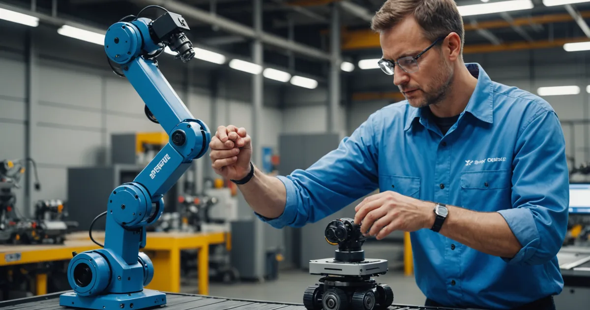
Hand guiding. The operator physically controls the arm's motion using a hand-guided input device, typically a wrist-mounted control ring or a grip-force-sensitive handle. The arm moves only while the operator is actively guiding it, at reduced speed, with force limiting active. This is the mode used during visual teach sessions. It is not a production collaboration mode; it is an interaction mode for programming and setup.
Speed and separation monitoring (SSM). The arm monitors the distance between its end-effector trajectory and any detected persons in the monitored space. As a person approaches, the arm reduces speed proportionally. If the person crosses the minimum separation distance threshold, the arm stops. This mode allows continuous arm operation in proximity to people, at the cost of slower cycle times when anyone is nearby. It requires a sensor system that can reliably track the human position in real time, typically a safety-rated 3D camera or lidar. SSM is the mode that enables genuine side-by-side work where the human and arm operate in overlapping space.
Power and force limiting (PFL). The arm operates with hard limits on the contact force and power it can apply at any point in its trajectory. If the arm contacts a person, the applied force is mechanically limited to values specified in ISO/TS 15066 as safe for the relevant body region. PFL-only deployment assumes incidental contact is possible and limits harm from that contact. It is typically combined with SSM, not used alone, because relying on contact-limiting alone means the arm will routinely contact people during normal operation, which is neither desirable nor acceptable in most production environments.
How zones are physically defined during commissioning
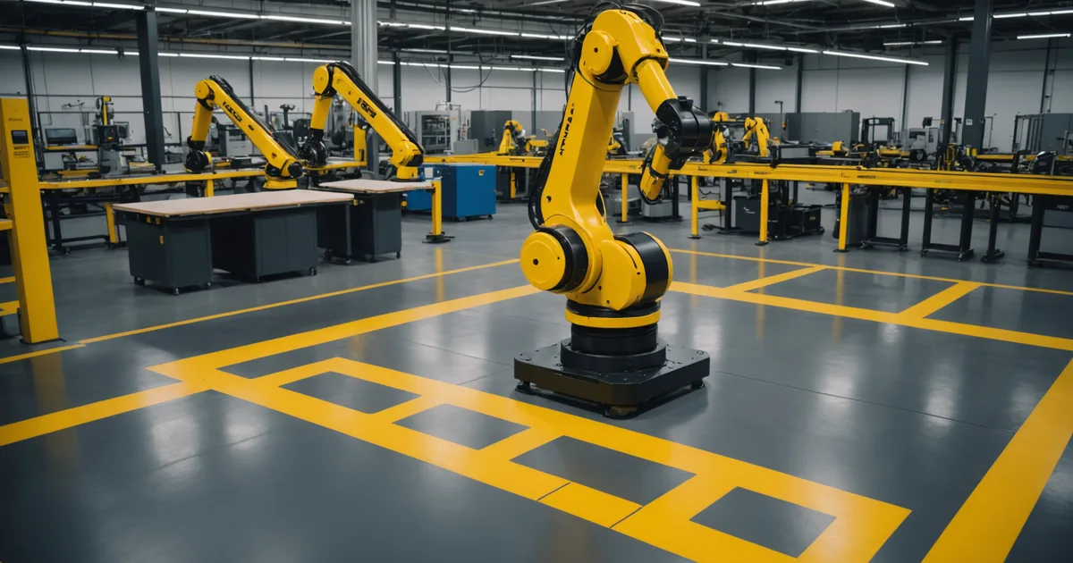
The term "safety zone" in most collaborative arm software refers to a geometric region around the robot base where the monitoring logic is active. This is not a physical fence. It is a monitored volume defined in the arm's coordinate frame. During commissioning, the integrator (or in our case, the plant's own operator during the initial setup session) sets the zone geometry to match the physical station layout.
For a typical pick-and-place station with a fixed fixture, the safety zone is usually a cylinder or a frustum around the robot base. The radius is set so that the outer boundary is comfortably outside the arm's maximum reach envelope, typically by 200 to 400mm. The height is set to cover the working height of the task plus the arm's maximum reach above the mounting surface.
During our commissioning process, we use the depth camera's live spatial map to assist in setting the zone geometry. The camera sees the fixed objects in the station, the conveyor, the fixture, the frame, and the operator can see in real time whether the proposed zone boundary has adequate clearance from those structures. This visual verification step matters: a zone set too tightly around the arm's reach can trigger nuisance stops from fixture components at the zone boundary. A zone set too loosely loses its protective function. Getting this calibration right requires knowing the actual geometry, not just plugging in default values.
One thing worth noting explicitly: the zone geometry is specific to the task. When the arm retasks from palletizing to pick-and-place, the safety zone gets recalculated as part of the commissioning for the new task, because the arm's motion envelope and the station geometry may have changed. This recalculation does not require a full re-commissioning from scratch, but it does require the operator to review and confirm the new zone before the arm enters production mode on the new task.
What actually happens when someone enters the zone
The specific response depends on which collaboration mode the station is configured for. For a safety-rated monitored stop setup, the sequence is straightforward: sensor detects person in zone, controller issues stop command, arm decelerates to a stop within the distance specified in the safety function, arm holds position until the zone clears and the operator initiates a resume.
For SSM, the response is proportional. The arm's speed profile is dynamically adjusted based on the calculated minimum separation distance at each moment in the trajectory. The speed scaling function follows from the ISO/TS 15066 formula for minimum protective separation distance, which accounts for the human's approach speed, the arm's current speed, a reaction time factor for the sensing system, and a stopping distance factor for the arm's braking capability. In practical terms: a person standing 600mm outside the zone boundary will cause the arm to reduce to perhaps 60 to 70 percent of its normal speed. A person at the inner boundary threshold will cause a stop. The exact percentages depend on the arm's specified braking performance and the sensing system's response latency.
For PFL, the arm continues operating but with force limits active throughout the trajectory. The ISO/TS 15066 biomechanical limits for quasi-static contact force by body region range from roughly 65 N for the head and neck down to around 140 N for the hand and finger region and up to 280 N for the thorax. These are not comfortable contact forces. They are limits that prevent injury. A well-designed collaborative arm station using PFL should not be routinely contacting people; the PFL limit is a last line of protection, not a design target for normal operation.
What this means for your commissioning and your operators
The single most common mistake in cobot safety zone commissioning is treating the zone parameters as a one-time configuration that never needs to change. On a fixed-task arm running the same part for three years, that may be approximately true. On an arm that retasks regularly, the zone parameters need to be reviewed every time the task changes, because the arm's motion envelope changes with the task.
Operator training for cobot stations is less about teaching people to be afraid of the arm and more about teaching them to understand what the arm will do when they enter its zone. In our experience, operators who understand the monitoring logic, that the arm will slow down as they approach and stop if they get too close, interact with the station more efficiently than operators who either ignore the arm entirely or treat it as unpredictably dangerous. The goal of the safety design is to make the arm's behavior in proximity to people predictable and proportional, not to make the arm dangerous or the zone a hard exclusion boundary at all times.
As a general caution: the safety behavior described here reflects the design intent of the monitoring and control systems as configured during commissioning. Actual safety outcomes depend on the quality of that commissioning, the condition of the sensing hardware, and whether the zone parameters have been correctly updated when the task changes. Validate on your specific cell before authorizing operator co-presence with any collaborative arm, regardless of what any vendor documentation describes in the abstract. The standards define the framework; your commissioning implements it for your specific station.
A note on what collaborative does not mean
Collaborative does not mean unguarded. It does not mean the arm is safe to work alongside without any configuration or commissioning. It means the arm's control architecture and physical design include features that support human-robot co-presence when those features are correctly implemented. An arm with PFL capability running at full speed without a functioning sensor system is not a safe collaborative installation, regardless of how the hardware is marketed. The standard defines what is needed for a compliant collaborative installation; the product enables it; the commissioning delivers it.
That distinction matters especially for plants considering first-time cobot deployments. The arm is one component of a collaborative cell. The station layout, the sensor system, the collaboration mode selection, the zone calibration, and the operator training all contribute to whether the cell is actually safe. Getting those elements right is where the deployment work is, not just in the hardware.